2X rotary vane vacuum pump schematic
2X rotary vane vacuum pump schematic
Figure (1) is a working principle diagram of a 2X rotary vane vacuum pump. The rotors 3 and 7 are tangent to the high vacuum outdoor 1 and the low vacuum chamber 6, and the rotors 3 and 7 are rotated in the direction of the arrow to drive the rotating tab in the rotor slot. Rotation, due to the action of the spring 9 and the centrifugal force, the outer end of the rotor slides close to the inner surface of the high and low vacuum chamber, and the moon-shaped space formed by the rotor and the high and low vacuum chambers from the intake nozzle 2 to the exhaust valve 5 and the slave The air pipe 4 is separated from the exhaust valve 10 to form two or three volumes, and the magnitude of the periodicity changes. When the rotary vane vacuum pump position continues to rotate, the A and C volumes gradually increase, and are drawn. The volume of gas does not enter the pump, and the volume of B and D gradually decreases, the pressure rises, and then the exhaust valves 5 and 10 are opened, and the gas is discharged outside the vacuum chamber, and the gas is discharged into the atmosphere through the oil surface because The oil floods the exhaust valve, thus preventing gas from returning to the vacuum chamber. When the pumping pressure is high, the valves of the high and low vacuum chambers are exhausted, which is equivalent to a single-stage pump. When the degree of vacuum is high, all the gas enters the vacuum chamber and is discharged by the exhaust valve 10. Enter the dual-stage pump to work.
If the gas to be extracted contains a higher vapor gas, when the gas is compressed and the partial pressure of the steam exceeds the saturation pressure of the steam at the pump temperature, the vapor is compressed into a liquid, and the rotary vane vacuum pump Can not be discharged, but mixed in the vacuum pump oil, so that the performance of the pump is greatly reduced, the impact of water vapor on the vacuum pump is very large. If the proper amount of air is mixed so that the partial pressure of the steam is lower than the saturation pressure of the pump temperature when the steam is compressed, the steam can be discharged outside the pump before it becomes a liquid, so the series 2X-4 or higher is rotated. The chip vacuum pump is equipped with an aeration valve 11 capable of inserting a certain amount of gas as shown in the following figure (1). 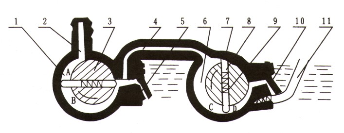
| 1 | High vacuum outdoor | 2 | Intake nozzle | 3 | Rotor | 4 | Gas pipe | 5 | Exhaust valve |
| 6 | Low vacuum chamber | 7 | Rotor | 8 | Blade | 9 | spring | 10 | Exhaust valve |
Shandong Longze Mechanical Equipment Co.,Ltd , https://www.pelletmachinefactory.com