CellSens standard software main function operation instructions
First, real-time image adjustment and photo preservation in bright field
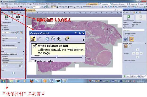
1. After opening the cellSens software, first switch the camera chip to “ color mode †in the camera control tool window. At this time, the camera automatically switches to the color chip for bright field image capture; then click “ real-time observation †to preview the sample. Then adjust the exposure mode to “ Auto †in the camera control tool window, and finally adjust the exposure mode to “ Manual †to obtain a satisfactory observation by increasing or decreasing the exposure time;
Â
2. If the background of the bright field image is not clean enough, you can perform white balance operation in the camera control tool window. Click “ White Balance †and then select the background area outside the sample in the preview image to perform white balance.
Â
3. According to the experimental requirements, adjust the resolution of the photo and click “ Photograph †to complete the timely preview of the current preview image. Save the image to the specified folder. The default save format of the image is “ TIF †format.
Second, fluorescence real-time image adjustment and photo preservation
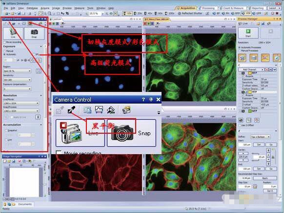
1. After opening the software, first switch the camera chip to “ Grayscale Mode †in the camera control tool window. At this time, the camera automatically switches to black and white chip for fluorescence image acquisition; next, select the advanced fluorescence mode “ SFL â€;
Â
2. Then click “ Real-time observation †to preview the fluorescence image, and select the appropriate fluorescence observation mode (such as DAPI, FITC) in the toolbar above the software to adjust the exposure mode to “ Auto â€, according to the intensity of fluorescence expression. You can switch the exposure mode to “ Auto â€, and increase the exposure time to make the fluorescence expression brighter, and vice versa; if the exposure time is more than 1s, you can increase the “ gain †value appropriately (the default is 1, you can adjust to 2) ) to make the shorter exposure time reach the same fluorescent brightness;
Â
*1. If you feel that the background of the fluorescent sample is not clean enough, you can perform the black balance operation. Click “ Black Balance †and then select the background area other than the fluorescent sample in the preview image to perform the black balance.
Â
*2, according to the experimental needs, adjust the resolution of the photo and click " photograph " to complete the timely preview of the current preview image, save the image to the specified folder, the default save format of the image is " TIF " format
Â
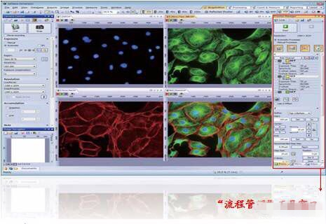
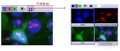
 Multi-channel image: Fluorescent image taken with a black-and-white camera chip + custom fluorescence observation mode. This image has been added by default in the software and uses the pseudo color of the corresponding channel. The image mode is " multi-channel, 16-bit image. ".
Third, multi-channel fluorescence automatic superposition (CS-ST+ MA)
1. Switch the tool window to the Process Management tool window;
2. Select the " Automatic Processing " option;
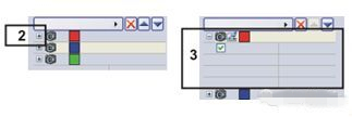
3. Click the " Multi Channel " button  , the button will be displayed as clicked, and the inside of the button will be filled with a light yellow background;
4. Click the Add Channel button  , the context menu is opened; the context menu will list all the observation modes of the current software settings (DAPI, FITC, CY3, CY5 and other fluorescence observation modes);
5. Select the color channel you want to capture first, such as the blue “FUWâ€, then click the small plus sign next to the first color channel to activate the current blue channel and press the software prompt to switch the filter wheel to 1 Number position
6. Then switch the tool window to the “ Camera Control †tool window, click “ Real Time View †to adjust the exposure time and gain value of the fluorescent sample to achieve an optimal observation effect; then switch to the “ Process Management †tool window. Click the Read Settings button to read the exposure time and gain value for the best observation effect to the currently activated fluorescence channel;
7. You can repeat steps 4-6 later to add other fluorescent channels that you want to combine with the currently activated channel (eg blue channel);
8. In the Process Management Tools window, click the Start button  , The software then prompts are sequentially switched different fluorescent color blocks, each camera will automatically switch to take a fluorescent image, to be designated multi-channel combination filter wheels after the handover is completed, the software automatically capture the different channels Multiple fluorescence images are superimposed on the fluorescence, and a superimposed fluorescence image of all channels is displayed in the image window;
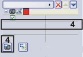
9. Save the multi-channel fluorescence image as the specified folder. The default file save format is “ TIF †format, which is saved in the original image;
10. If you need to save the fluorescence image under a single channel, click the “ tiling †button, place the mouse on the image of the single fluorescence channel you want to save, right click on “ Extract †and the software will separate the fluorescence image of the channel. Extract it; click “ Image †> “ Print Information †> and select “ Yes †to save the fluorescent image, then you can get a fluorescent image containing pseudo color information. The image format is recommended as “ TIF â€. format.
Fourth, the ruler information display and preservation
If you want to display and save the ruler information in the software, you can click “ View †> “ Scale †when previewing the image, the ruler will be displayed on the image; then click “ Photograph â€, after the photo is completed, click “ Image †">" Print Information " > and select " Yes " to save the image, the ruler information will be printed on the image.
Five, manual large picture stitching (CS-ST+MPC)
1. Switch the tool window to the Process Management tool window;
2. Select the " Manual Processing " option;
3. Click the " Manual Image Stitching " button  , the button will be displayed as clicked, and the inside of the button will be filled with a light yellow background;
4. Make sure the Auto Align button is displayed as clicked. The button should appear as 
;
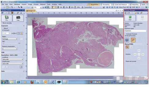
5. In the Process Management Tools window, click the Start button The software will switch to the real-time observation mode. After the sample is clearly focused, the stage can be moved so that it appears in the field of view from the upper left corner of the sample;
6. Click on an arrow button to set which side of the current image you want to arrange next when you click  When the arrow is used, the software will automatically capture the current sample image appearing in the image window, and the current real-time image will appear on the right side of the captured image. By moving the stage, the upper right corner of the sample in the real-time image and the upper left corner of the sample are collected. The images overlap; then click
  When the arrow is used, the image of the left and right parts of the current sample will be collected, and then the current real-time image will appear below the captured image. By moving the stage, the sample in the real-time image will coincide with the captured image in the lower right corner; Repeatedly until a complete sample is completely spelled out;
7. Save the stitched image as the specified folder. The default file save format is “ VSI †format.
Â
Sixth, manual depth of field expansion (CS-ST+MPC)
1. Switch the tool window to the Process Management tool window;
2. Select the " Manual Processing " option;
3. Click the " Expand depth of field " button  , the button will be displayed as clicked, and the inside of the button will be filled with a light yellow background;
4. Select the transmission (exponential/quadratic function) for the bright field image when the depth of field is extended, and select the reflection (exponential/quadratic function) when the fluorescence image expands the depth of field;
5. In the Process Management Tools window, click the Start button In this case the lower right of the screen image window is the current real-time image focal plane of the sample, while the lower screen image on the left window is the current information of the focal plane of the sample, the slow process of trimming, sequentially achieve different focal plane of the sample After using the fine adjustment mechanism to move from the lower focal plane of the sample to the upper focal plane, all the sample information on different focal planes will be fully accumulated in the left image below the image window; and a different one will be automatically generated at the top of the image window. The superimposed image of the focal plane sample information, then click the stop button  The image window will generate a full picture with a clear overlay; click File > Save As command to save the new image. Always use the TIF or VSI file format when saving images.
Seven, time interval photo
1. Activate the process management tool window;
2. Select the " Automatic Processing " option;
3. Click the "time limit " button  , the button will be displayed as clicked, and the inside of the button will be filled with a light yellow background;
4. Specify the time required to complete the acquisition, such as 10 seconds. Enter the value " 00000:00:10 " (that is, 10 seconds) in the Recording Time field. You can edit each number directly in this field. To do this, just edit it
Click once before the number;
5. Select the radio button to the right of the data segment to specify the acquisition time as no longer changing.  The lock icon will automatically appear next to the selected radio button;
6. Specify the number of frames you want to capture. Enter in the Cycles field, for example 10, and the interval field will be updated. It represents the elapsed time between two consecutive frames;
7. In the Process Management Tools window, click the Start button , the time series will begin to be collected immediately;
8. The Start Process button will then change to the Pause button, which will interrupt the acquisition process;
· The stop button will become active. Clicking this button will stop the acquisition process, and the time stack image collected until then will be retained;
· A progress bar will appear in the status bar at the bottom left of the image window, which will tell you how many more images you need to capture;
9. When you see the Start button again in the Process Management Tool window and the progress bar disappears, the acquisition is complete; save the time series image as a specified folder, and the default file save format is “ VSI †format.
PTFE Coated Guide Wire,Guide Wire,hydrophilic guide wire,medical guide wire
Anesthesia Medical Co., Ltd. , https://www.medicaldiverse.com